Difference between revisions of "RFID"
| Line 3: | Line 3: | ||
A self-built RFID reader is connected to the DS via [[DSerial]]. It is part of the project "Nordlich BlitzPlay (RFID Guitar Hero III)". For details and concept of this pervasive game, please take your time and look at the website: http://www.ludic-society.net/blitz! | A self-built RFID reader is connected to the DS via [[DSerial]]. It is part of the project "Nordlich BlitzPlay (RFID Guitar Hero III)". For details and concept of this pervasive game, please take your time and look at the website: http://www.ludic-society.net/blitz! | ||
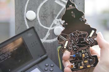
| + | [[Image:Dserial_RFID_level3.jpg|thumb|400px|none|Street Play Performance]] | ||
The signal lines are connected to DSerial CMOS-level [[UART]] at [[IO|IO2]] connector. Make sure to set baud rate to 9600baud. Please, make sure that you edited also mcu.h and the firmware according to the "Hello World LED" example (link). | The signal lines are connected to DSerial CMOS-level [[UART]] at [[IO|IO2]] connector. Make sure to set baud rate to 9600baud. Please, make sure that you edited also mcu.h and the firmware according to the "Hello World LED" example (link). | ||
| Line 56: | Line 57: | ||
== Pictures == | == Pictures == | ||
| − | |||
| − | |||
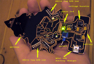
[[Image:Dserial_RFID_tree.jpg|thumb|400px|none|Wunderbauemchen Description]] | [[Image:Dserial_RFID_tree.jpg|thumb|400px|none|Wunderbauemchen Description]] | ||
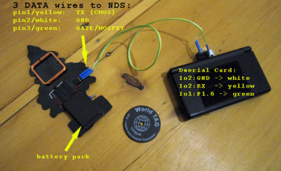
[[Image:Dserial_RFID_nds.jpg|thumb|400px|none|Wire Plan]] | [[Image:Dserial_RFID_nds.jpg|thumb|400px|none|Wire Plan]] | ||
Revision as of 23:33, 30 November 2007
Contents
Description
A self-built RFID reader is connected to the DS via DSerial. It is part of the project "Nordlich BlitzPlay (RFID Guitar Hero III)". For details and concept of this pervasive game, please take your time and look at the website: http://www.ludic-society.net/blitz!
The signal lines are connected to DSerial CMOS-level UART at IO2 connector. Make sure to set baud rate to 9600baud. Please, make sure that you edited also mcu.h and the firmware according to the "Hello World LED" example (link).
Here is some sample code of the UartHandler: <cpp> int ledTimer = 10; void uartReceiveHandler(char * data, unsigned int size);
void uartReceiveHandler(char * data, unsigned int size) {
 if((size > 0) && (size <= MAX_DATA_SIZE)){
   char buffer[MAX_DATA_SIZE+1];
   memcpy(buffer, data, size);
   buffer[size] = '\0';
   iprintf(buffer);
 }
}
/* during initalization do following */
dseUartSetBaudrate(9600); dseSetModes(ENABLE_CMOS /* | ENABLE_SERVO */); dseUartSetReceiveHandler(uartReceiveHandler);
/* then somewhere else within the while(1) do: */
if (ledTimer>0) ledTimer--; if (ledTimer==0) {
ledTimer=-1;
{
 ledTimer=-1;
 uint8 p1 = dseReadRegister(MCU_P1);
 dseWriteRegister(MCU_P1, p1 | 0xC0);
} if (ledTimer<0) { ledTimer=-1; }
</cpp>
Schematic
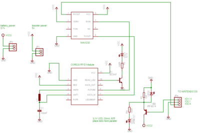
The gate of NPN Mosfet is connected to PIN 6 of DSerial's IO1
Parts
- [1] Core20 RFID Reader Module (works at 5Volt!)
- [2] IRF9014 MOSFET
- MAX232
- SMD Parts (Resistors, Capacitor, Coil)
