Difference between revisions of "Bootloader"
(→Unlocking) |
|||
| Line 6: | Line 6: | ||
* Boot DSerial [[firmware]] | * Boot DSerial [[firmware]] | ||
* Return [[firmware]] version | * Return [[firmware]] version | ||
| − | * Upgrade [[firmware]] via SPI | + | * Upgrade [[firmware]] via SPI (other ports may be supported by the bootloader in the future) |
The following sections will describe how the bootloader functions. | The following sections will describe how the bootloader functions. | ||
| − | == | + | == Detecting DSerial == |
| − | + | Check whether DSerial is inserted using a [http://www.st.com/stonline/books/pdf/docs/10823.pdf SPI Flash] compatible command: | |
# DS sends the byte 0x9F (RDID) | # DS sends the byte 0x9F (RDID) | ||
| Line 18: | Line 18: | ||
| − | + | This is command is non-destructive to DS game cards. | |
| − | |||
| − | |||
| − | |||
== Interrupt Vector Table == | == Interrupt Vector Table == | ||
Revision as of 21:24, 3 January 2007
Overview
The purpose of DSerial bootloader is to:
- Boot DSerial firmware
- Return firmware version
- Upgrade firmware via SPI (other ports may be supported by the bootloader in the future)
The following sections will describe how the bootloader functions.
Detecting DSerial
Check whether DSerial is inserted using a SPI Flash compatible command:
- DS sends the byte 0x9F (RDID)
- DSerial responds with 0x9F 0x01 0xAB
This is command is non-destructive to DS game cards.
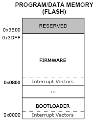
Interrupt Vector Table
Interrupt vector table on the C8051F320 is always at offset 0 in FLASH. Unfortunately, we cannot re-target it from bootloader interrupt vector table into the program interrupt vector table with a magic register, since no such register exists in the architecture. Instead, we have to re-target each interrupt separately.
The following code shows how it's done in DSerial bootloader.
<cpp> // Code in bootloader
// Redirects UART IRQ either into our (bootloader's) handler or into firmware handler. void R_uartInterrupt() __interrupt (4) _naked { _asm mov a, _IrqVector ; compare IrqVector to 0 jnz 00001$ mov a, (_IrqVector+1) jz 00002$ 00001$: ; if not 0, then we need to jump to it mov dpl, _IrqVector mov dph, (_IrqVector+1) mov a, #0x23 ; this is the offset for uart irq jmp @a+dptr ; call the interrupt handler in firmware 00002$: ; if it's 0, then we'll handle the irq lcall _uartInterrupt ; call our own interrupt handler reti _endasm; }
// repeat for the other irqs </cpp>
IrqVector is a global variable that is set to the location of interrupt vector before enabling interrupts. The bootloader should set IrqVector to 0 while the program should set it to it's location.
<cpp> // Code in firmware
__data __at (0x7e) unsigned int IrqVector;
void main() { // ... IrqVector = 0x0800; // we're relocated to 0x0800 EA = 1; // global interrupt enable // ... } </cpp>
Note: It would also be possible to use the User Bit in PSW register instead of IrqVector. It would be less flexible, but would result in a smaller overhead in redirection. Should be considered for future bootloader and firmware.
