Difference between revisions of "MIDI"
| (13 intermediate revisions by 3 users not shown) | |||
| Line 1: | Line 1: | ||
| + | == Description == | ||
| + | |||
| + | MIDI devices are very easy to connect to DS via [[DSerial]]. MIDI Out can be directly wired to the connector without any components. MIDI In requires to use an [http://en.wikipedia.org/wiki/Optocoupler Optocoupler], but the schematic is quite simple. | ||
| + | |||
| + | The signal lines should be connected to DSerial CMOS-level [[UART]] at [[IO|IO2]] connector (do not use RS-232). Sending and receiving is done using the UART commands. Make sure to set baud rate to 31250bps as this is what MIDI is using. | ||
| + | |||
| + | Here is some sample code to send a note: | ||
| + | <cpp> | ||
| + | void midiWrite(u8 message, u8 data1, u8 data2) { | ||
| + | u8 buffer[3]; | ||
| + | buffer[0] = message; | ||
| + | buffer[1] = data1; | ||
| + | buffer[2] = data2; | ||
| + | dseUartSendBuffer((char *) buffer, 3, true); /* blocking UART send */ | ||
| + | } | ||
| + | |||
| + | /* then somewhere else do: */ | ||
| + | |||
| + | dseSetModes(0); /* Disable RS-232 */ | ||
| + | dseUartSetBaudrate(31250); /* MIDI baudrate is 31250 bps */ | ||
| + | |||
| + | midiWrite(0x90, 0x11, 0x22); /* send a note to MIDI keyboard */ | ||
| + | </cpp> | ||
| + | |||
== Schematic == | == Schematic == | ||
| − | [[Image:Midi-schematic.gif|DSerial MIDI In/Out Schematic]] | + | [[Image:Midi-schematic.gif|thumb|400px|none|DSerial MIDI In/Out Schematic]] |
| + | |||
| + | Parts | ||
| + | *[http://www.fairchildsemi.com/pf/FO/FOD260L.html FOD260L] optocoupler (3.3V, most other optocouplers are 5V...) | ||
| + | *1N4148 switching diode | ||
| + | *220 Ohm resistor. | ||
== Pictures == | == Pictures == | ||
| Line 8: | Line 37: | ||
[[Image:Midi-pcb-top.jpg|thumb|400px|none|MIDI Input requires an Optocoupler IC]] | [[Image:Midi-pcb-top.jpg|thumb|400px|none|MIDI Input requires an Optocoupler IC]] | ||
[[Image:Midi-pcb-bottom.jpg|thumb|400px|none|Small PCB for MIDI input]] | [[Image:Midi-pcb-bottom.jpg|thumb|400px|none|Small PCB for MIDI input]] | ||
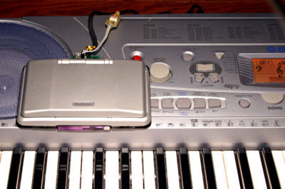
| + | [[Image:Midi-keyboard.jpg|thumb|400px|none|MIDI keyboard connected to DSerial]] | ||
== PCB == | == PCB == | ||
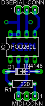
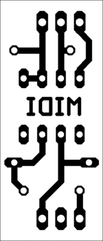
[[Image:Midi-pcb-placement.gif|thumb|150px|none|Component placement]] [[Image:Midi-pcb-600dpi.gif|thumb|150px|none|PCB 600dpi]] | [[Image:Midi-pcb-placement.gif|thumb|150px|none|Component placement]] [[Image:Midi-pcb-600dpi.gif|thumb|150px|none|PCB 600dpi]] | ||
Latest revision as of 22:38, 9 September 2010
Contents
Description
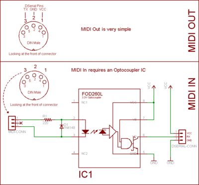
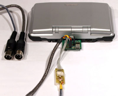
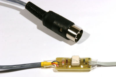
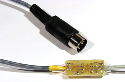
MIDI devices are very easy to connect to DS via DSerial. MIDI Out can be directly wired to the connector without any components. MIDI In requires to use an Optocoupler, but the schematic is quite simple.
The signal lines should be connected to DSerial CMOS-level UART at IO2 connector (do not use RS-232). Sending and receiving is done using the UART commands. Make sure to set baud rate to 31250bps as this is what MIDI is using.
Here is some sample code to send a note: <cpp> void midiWrite(u8 message, u8 data1, u8 data2) { u8 buffer[3]; buffer[0] = message; buffer[1] = data1; buffer[2] = data2; dseUartSendBuffer((char *) buffer, 3, true); /* blocking UART send */ }
/* then somewhere else do: */
dseSetModes(0); /* Disable RS-232 */ dseUartSetBaudrate(31250); /* MIDI baudrate is 31250 bps */
midiWrite(0x90, 0x11, 0x22); /* send a note to MIDI keyboard */ </cpp>
Schematic
Parts
- FOD260L optocoupler (3.3V, most other optocouplers are 5V...)
- 1N4148 switching diode
- 220 Ohm resistor.
