Serial Interface for PassMe
Description
This interface allows to connect PassMe to the computer and to other devices. Connection to the computer can be through RS-232 (serial com port), USB and bluetooth.
Other devices that can be connectod are PDA keyboards, data modems, servo and motor controllers, GPS modules, radio data transmitters, etc...
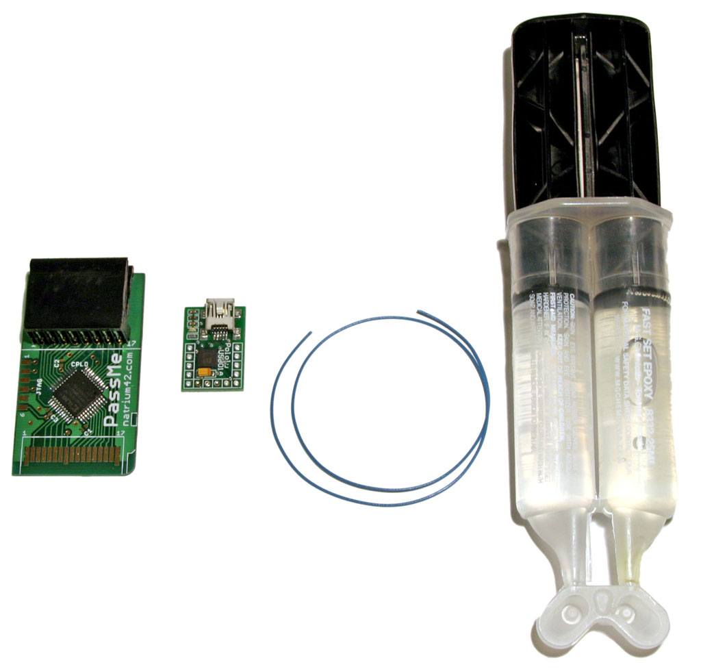
Parts needed
- JTAG cable for Xilinx CPLDs such as Cheaptag
- Desired communication module (USB, USB2, Bluetooth, etc...)
- Some wire
- 4-pin connector (optional)
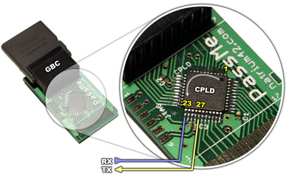
Diagram
Construction
The chip on the PassMe has to be reflashed for this project. You can build the programming cable for your printer port by following instructions available here.
Flash with the JED file from the ZIP available on the bottom.
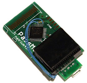
Solder the two wires shown in the diagram to the CPLD. Put a blob of Epoxy glue onto this connection so that the wires don't get lose. Solder one wire to pin 1 or pin 17 of the GBC. This wire is ground (minus -).
If your communication module needs power, you can get 3.3V from pin 8 of the GBC.
Connect RX of PassMe to TX of your communication module. Connect TX of PassMe to RX of your communication module.
It's best to use some 4-pin connector so that you can change communication modules easily. Don't forget to connect the grounds of PassMe and the module.
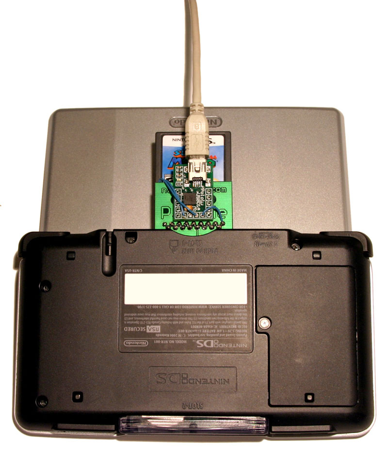
Example #1
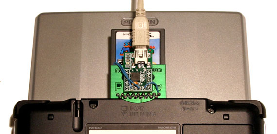
Here is an example with the USB-to-serial module available from Pololu. I soldered the wires directly to the module and didn't use a connector.
This gives a smaller package, but makes changing communication modules hard.

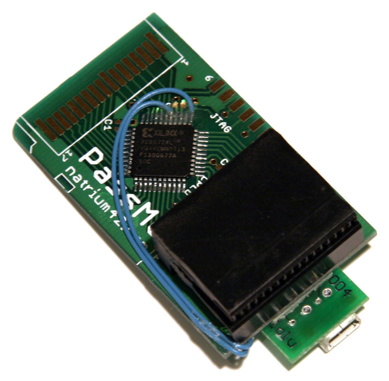
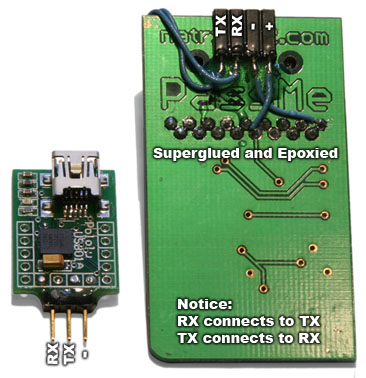
Example #2
Same as first example but with a connector. This allows to connect other communication modules such as a bluetooth module.
Notice that this given USB module doesn't need power from PassMe since it takes power from USB.
Usage
Here is some ugly ARM7 sample code for accessing serial port and the file for CPLD flashing: passme-serial.zip